Using the information from Part 1, the basics of electro-etching are introduced.
6. Metal plates immersed in electrolytes –towards electro-etching
6.1 A zinc plate in zinc sulphate solution
If a plate of zinc is placed in a beaker containing a solution of zinc sulphate – a “zinc half- cell” - outwardly not much appears to happen.
However, at the instant of placing the plate in the solution, at the surface of the zinc some zinc atoms discard their outer electrons and move into the solution. Electro-neutrality no longer exists at the plate/solution interface: there is now an excess of
Zn ++ ions in the solution adjacent to the plate (originally there are equal numbers of
Zn ++ and
(SO4) −
− ions in the electrolyte) and an excess of electrons (negative charge) on the plate. Very quickly, this imbalance causes a flow of Zn ++ ions back to the plate to match the flow away from the plate. In this dynamic equilibrium there is no further net loss of zinc from the plate and the resultant total current is zero.
Overall, there is a negligible loss of weight in the zinc plate but there is a significant and permanent change: an excess of electrons on the plate surface and an excess of positive zinc ions in the electrolyte very close to the metal - at the metal/electrolyte interface - remain. These surfaces of equal and opposite charge form a “double layer”. The bulk of the electrolyte maintains electro-neutrality but the excess charge due to the double layer gives the metal surface a negative electric potential with respect to bulk of the electrolyte; the potential difference is around 0.5 volts.

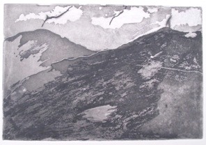
Test print showing different depths of natural “electro-tint”
obtained by masking out copper plate with nail varnish;
electro-etch with copper sulphate
6.2 A copper plate in copper sulphate solution
For an equivalent copper half-cell with copper sulphate solution, the effect is essentially the same as for the zinc plate: a dynamic equilibrium is rapidly attained and a double layer due to excess charges is set up. In the case of copper, the equilibrium condition corresponds to a negligible mass of Cu++ ions from the electrolyte sticking on the metal surface to give it a positive electric potential with respect to the bulk electrolyte; the potential difference is again around 0.5 volts.
Electric potential difference: suppose we have two metal conductors of the same size, say, copper spheres A and B. On sphere A there are (say) a million excess electrons while on B there are only a thousand excess electrons – let’s not concern ourselves about how the electrons arrived on each sphere and clearly the electro-neutrality condition does not apply. Then we can say that sphere A has a negative electric potential with respect to sphere B, or equivalently there is a potential difference VAB between A and B.
If sphere B has no excess charge or a positive excess charge, such a potential difference will still exist and we can generalise for electric conductors other than metal spheres of the same size: the potential difference could be between a charged plate and the liquid electrolyte in which it is immersed.
If the two spheres are now joined together with a metal wire, very quickly electrons will flow from A to B until they have equal numbers of electrons at which point the two spheres will have the same electric potential – there is no longer a potential difference.
7. The basis of the saline sulphate/Bordeaux etch - mixing it up
7.1 Zinc plate in copper sulphate solution – displacement reaction
When a zinc plate is placed in copper sulphate solution something definitely happens! Spontaneously, zinc atoms at the metal surface leave electrons on the plate and move into solution as Zn ++ ions; simultaneously copper Cu++ ions are attracted to the plate. The zinc ions “displace” the copper ions and this time there is no charge imbalance in the solution or at the metal surface so the reaction can carry on. The deep colour blue of the copper sulphate solution will gradually fade (zinc sulphate is colourless); the zinc is eaten away and a layer of copper forms on the zinc plate – the copper is “plated out”. With this reaction heat is produced and in practice some hydrogen gas may be produced from a side reaction involving the water.
This reaction is a spontaneous “reduction – oxidation reaction” (Redox):
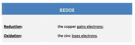
Classical thermodynamics can predict the outcome of such reactions but not the dynamics of the reaction - how fast it happens - which in detail may be very complicated.
The reaction may be recognised as the basis for the widely used saline sulphate/Bordeaux etching processes (see “The saline sulphate etch and Perfect chemistry” by Friedhard Kiekeben on his website and “Bordeaux etch” by Cedric Green on his website). In practice, particularly for aluminium, there may be an oxide coating on the metal plate which can effectively seal the surface. If sodium chloride is added to the solution, the chloride ions can break up this oxide surface. Due to the spontaneous nature of the reaction, chemistry rather than the etcher is in control.
8. The voltaic cell
8.1 The classic Daniell voltaic cell-taking the heat out of displacement reactions.
Although the displacement reaction just described provides a useful etching technique, for others purposes it is wasteful because the energy liberated during the process only heats the electrolyte. Far better would be to use this energy to push electrons through an external electric circuit to do useful work like driving an electric motor. Such a device, a voltaic cell, can be made by combining the zinc and copper half-cells – a Daniell cell, see figure 3 below. In effect the redox reaction is split into its reduction and oxidation reactions with each one now taking place in separate containers which are connected electrically by a salt bridge. The energy generated in the reactions is manifested as electrical energy not heat.
To describe the action, suppose that a small “pea” light bulb and switch are connected electrically between the two plates and the electrolytes in the half-cells are joined by a salt bridge. With such a “completed” circuit, when the switch is closed a current flows lighting up the bulb.
Test print: tone obtained with conventional aqua-tint; electro-etch, copper plate, copper sulphate electrolyte; masking out with candle
There is no further build-up of excess charge beyond that required for the original equilibrium condition for each half-cell and so the dissolution of the zinc plate continues unimpeded. Simultaneously, in the copper half-cell the concentration of the copper sulphate solution gradually reduces as copper ions from the solution stick on the plate, acquire the excess electrons which have flowed from the zinc plate and then “plate out” as a film of copper atoms. An electric potential difference is maintained between the plates; this can be measured under conditions of virtually zero electric current - the spontaneous dynamic equilibrium condition discussed earlier – with a high resistance voltmeter.
As the zinc plate is progressively consumed and the copper sulphate solution weakens, the potential difference decreases and eventually the cell stops working. The possible combinations of metals which can be used in voltaic cells and the “passive” etching described below may be determined from the so-called electro-chemical series, see Appendix A, section A1.3.
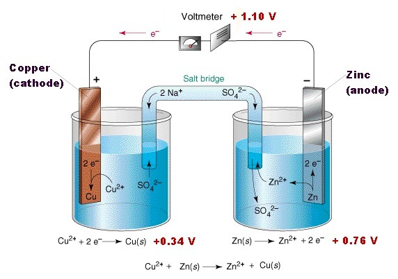
Figure 3: An example of a Daniell cell, from the Chem1 Virtual textbook by Stephen Lower
www.chem1.com/acad/webtext/virtualtextbook.html
Modern batteries use solid rather than liquid electrolytes and consist of multiple cells to improve the current and voltage characteristics. The term” battery” was introduced by Benjamin Franklin, by analogy with a battery of cannons, to describe cells connected together.
In general when a battery is connected to an electrical circuit:
+ terminal accepts electrons from the circuit
− terminal pumps electrons into the circuitFor safety, the terminals of a battery should not be connected together by just a wire, “shorted”:
a large current may flow in the wire causing it to get very hot.

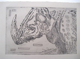
Test print: creating tone with cross hatching; electro-etch,
copper plate, copper sulphate electrolyte;
candle wax ground; After Cartier-Bresson
9. From voltaic cell to passive electro-etching.
The inherent mechanism of the classic voltaic cell - dissolving of the zinc - can be used to advantage to etch the zinc plate – passive etching - with some degree of control: the switch can be used to stop and restart the etching process. However the arrangement described above is not very practicable as it requires three electrolytes.
A simpler system for etching a zinc plate where the zinc and copper plates are placed in a single electrolyte of copper sulphate and the plates are joined together by a wire has been described by Cedric Green (see website) and Alfonso Crujera, who also included a sodium chloride reservoir add-on – see the English edition of his electro-etching book. This would appear to be a hybrid of the basic displacement reaction in a single container and the passive electro-etching.
The characteristics of this etching technique are discussed by Cedric Green and Alfonso Crujera who has obtained comparatively short biting times when using the additional salt reservoir. The major disadvantage of this technique and the saline sulphate/Bordeaux etching is that the copper sulphate electrolyte becomes gradually exhausted so etching times will change and at some point the solution must be replaced.
With one further step it is possible to obtain an etching process which is both controllable and does not exhaust the electrolyte which can be used for years without replacement –active electro-etching.
10. Active electro-etching: the electrolytic cell
10.1 Taking control: using a power supply to drive an electrolytic cell
10.1.1 Pumping water
The analogy of a water reservoir on a hill feeding a tank at the bottom of the hill provides a convenient way of introducing the principle of “active electro-etching”. Imagine that the water reservoir represents the zinc plate, the tank represents the copper plate, the pipe between them is equivalent to the connecting wire and the flow of water is the electron current. The water-flow is due to the gravitational potential difference –the height of the reservoir above the tank – while the electron flow is due to the electric potential difference obtained by using two different metals. In both cases, the flow rate gets larger as the potential difference is increased.
If an in-line water pump is added, the water flow downhill can be increased or the flow can be reversed and water pumped uphill. The flow of water is now determined mainly by the pump rather than the height of the reservoir above the tank and the flow rate can be changed by altering the pump settings.
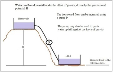
Figure 4: Pumping water - an analogy for elctro-etching cells
10.1.2 Pumping electrons
Similarly for the electrical system, an “electron pump” can be used to increase the electron flow or even reverse it and the need for dissimilar metal plates to provide a potential difference is not necessary. The “electron pump” is of course a battery or direct current power supply and the pumping capacity is determine by the battery’s voltage –the potential difference between the positive and negative terminals. For etching purposes, 0.5 -2 volts are generally sufficient but the current requirement may range from several tens of milli-amperes to tens of amperes for large plates. Larger voltages may introduce unwanted reactions, see later.

Copper test plate; electro-etch,
copper sulphate electrolyte, ground: candle wax;
After Talbot-Kelly
10.2 An electrolytic cell
A basic cell - an electrolytic cell – for, say, copper consists of two copper plates in a single container holding a copper sulphate solution electrolyte. The plate which is etched - the anode - gives up electrons to the positive terminal of the battery while at the negative terminal of the battery an equal number of electrons are pumped to the other plate – the cathode.
The process, known as electrolysis, is for us active electro-etching.
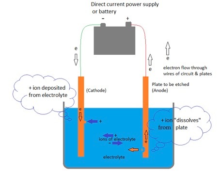
Figure 5: Schematic of an electrolytic cell: the plate to be etched is the anode, connected to the + terminal of the power supply.
When the power supply is turned on the electro-chemical process for an atom of copper is:
At the anode: a Cu atom gives up two electrons to the external circuit and dissolves in the adjacent electrolyte as a copper ion Cu++;
At the cathode: the cathode receives two electrons from the anode via the battery; a Cu++ ion attached to the plate accepts the two electrons and the copper atom produced adheres to the plate – it “plates out” onto the electrode;
In the electrolyte ( Cu++ ions and sulphate ions
(SO4) −
−): it gains a Cu++ ion from the dissolving copper anode and loses a copper ion Cu++ to the cathode – overall the electrolyte stays electro-neutral with no loss of copper or sulphate ions.
The dissolution (dissolving) of the copper atoms provides the basis for the etching process, now driven by an external power supply.
The simple image of an electron flowing around a circuit from the positive to the negative terminal of a battery is convenient but strictly incorrect. In fact electrons drifts quite slowly along a metal wire, typically they would take an hour to travel about 20 cm. Movement of electrons is due to their repulsive interaction: an excess of electrons at the anode can interact with all other electrons in the circuit and almost instantaneously cause the movement of electrons at the other end of the wire to the cathode. A similar effect will apply to ions in an electrolyte.
10.3 Active electro-etching with metal/same metal salt electrolyte.
Similar cells may be used for etching zinc and iron/steel plates using zinc sulphate and iron sulphate solutions as electrolytes. Again, provided the voltage is kept to below 2-3 volts the electrolyte remains essentially unchanged. This assumes that the operating conditions are such that the amount of metal deposited on the cathode is equal to, or practically equal to, the amount removed (etched ) from the anode plate. In principle, depending on the condition of the cathode plate, it is possible for hydrogen gas to be formed there by a secondary reaction and appear as fine bubbles (see Appendix A, sections A2.4 and A2.6). Typically, for active electro-etching this effect does not appear to happen or is small enough not to be seen (see Green and Crujera). Should it occur, however, then adequate ventilation must be provided to permit the safe dispersal of the hydrogen to the outside atmosphere.
Aluminium plates immersed in an aluminium sulphate solution would not electro-etch in a similar manner to the copper plates because the aluminium in solution cannot be deposited onto the cathode, see appendix A, section A2.5.
10.4 Practical electro-etching
For the beginner, electro-etching of copper, although not the cheapest option, is a good starting point. The use of iron/mild steel is attractive because both the metal sheet and the ferrous sulphate are relatively inexpensive compared to the other metals/electrolytes and the etched plate is durable because of its hardness.
After Drürer
Active electro-etching of copper, zinc or iron/mild steel plates provides a wide range of effects to satisfy the needs of many etchers and the present simplified explanation should provide an adequate physical background. Many readers need go no further. Detailed guidance on the practicalities can be found in “Electro-etching handbook –a safe, non-toxic approach” by Alfonso Crujera and on Cedric Green’s web-site.
Recently, interest has been shown and work undertaken to electro-etch aluminium and other metals using sodium chloride solution as an electrolyte, see for example, ”Aluminio una opcion de bajo costo para grabado -Aluminium a low cost option for Intaglio” by Francisco Hernández –Chavarria, El Artista, nº 9, 256 – 266 (2012) and “Printmaking Revolution – new advancements in technology, safety, and sustainability” by Dwight Pogue, Watson -Guptill. Attractions include the comparative low cost of aluminum and common salt and the natural “electro-tint” effects which can easily be obtained without the need for traditional aqua-tinting methods. The practical electro-etching techniques used are the same. The use of this electrolyte makes the electro-chemical process more complicated and in some people’s view is undesirable. In section 3 and appendix B we will discuss its features.
10.5 A small digression –going a little further.
So far we have considered active electro-etching of metals at low voltages with an electrolyte made from a salt of the same metal. There are aspects of electro-etching that require a little more understanding of the basic electro-chemistry through the use of so-called electro-chemical “standard potential tables”, for example:
• the electro-chemical series;
• why do some metals plate out on the cathode while others cannot;
• under what conditions will hydrogen gas evolve at the cathode;
• the characteristics of etching with sodium chloride solution,
• passivity – why the current can decrease as the voltage is increased;
Conscious that this may not be everybody’s “cup of tea” on a first of reading, the topic of standard potentials and some of the insights which it provides have been placed in appendix A – it contains some important topics.
For now, it is sufficient to learn that in an electro-etching cell using an external power supply there may be spontaneous reactions, typically the corroding of the anode – the plate undergoing etching - and non-spontaneous reactions, typically the evolution of hydrogen, chlorine or oxygen gas at the electrodes.
The key point is that spontaneous reactions are the “preferred reactions”: they are more likely to occur than non-spontaneous reactions; however should both occur then the spontaneous reactions will generally be the dominant electro-chemical reactions. Each reaction has its own “standard potential” - a certain number of volts, and in front of the number can be placed a (+) to denote a spontaneous reaction or a (-) to denote a non-spontaneous reaction.
Given a list of hypothetical reactions and associated standard potentials:
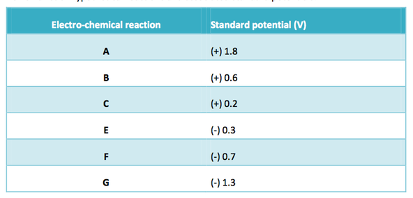
Reactions A to C are spontaneous; reactions E to G are non-spontaneous. The likelihood of a reaction occurring and its dominance may be ranked as:
Reaction A > B > C > E > F > G (> means greater than).
These considerations are based on thermodynamic principles which sometimes will be overruled by the chemical ”kinetics” of the reactions –how fast the reaction takes place.
NEXT - Part 3 - Electro-etching with Sodium Chloride Solution as the Electrolyte
Text © A Crujera and R M Perkin